Complex plumbing manifolds in filtration setups introduce multiple failure points, increase hydraulic friction, and inflate installation costs. Facility managers and pool builders often struggle with equipment pad spatial constraints and the ongoing maintenance liabilities associated with convoluted side-mount or detached valve configurations. When you have limited square footage on a concrete equipment pad, every inch matters. Bulky external pipe webs make routine maintenance difficult and increase the risk of joint leaks over time. Integrating the multiport valve directly onto the tank apex fundamentally alters plumbing architecture. This approach offers a streamlined method for routing a swimming pool filtration system. By moving the control hub to the top of the vessel, you eliminate the need for external PVC manifolds. This structural shift reduces dynamic head pressure and simplifies daily operations. We will break down exactly how this configuration optimizes your equipment pad layout and improves overall hydraulic efficiency.
Reduced Plumbing Complexity: Top-mounted valves eliminate the need for external PVC manifolds, significantly reducing the number of required elbows, unions, and potential leak points.
Optimized Spatial Footprint: Consolidating the valve and tank into a single vertical column frees up critical horizontal space on the equipment pad.
Hydraulic Efficiency: Shorter, more direct pipe runs from the pump to the filter intake reduce dynamic head pressure and friction loss.
Implementation Trade-offs: While piping is simplified, top-mount configurations require specific vertical clearance for valve removal and sand bed maintenance, dictating specific installation environments.
The Mechanics of a Top Mount Sand Filter in a Swimming Pool Filtration System
Problem Framing (Success Criteria)
An efficient filtration loop requires minimal pressure drop, accessible controls, and leak-resistant joints. Complex setups often fail these criteria by creating unnecessary friction and demanding excessive horizontal space. A well-designed system minimizes external piping, keeping water moving smoothly from the pump discharge to the return jets. Every sharp 90-degree turn reduces flow efficiency and adds feet of head to the total dynamic head calculation. Every glued joint introduces a potential failure point that can develop pinhole leaks under pressure. Success means achieving required turnover rates easily without overworking the pump motor. It means keeping the mechanical room organized so technicians can navigate the space safely. It also means reducing the time spent on routine maintenance like backwashing or winterizing the equipment. When you eliminate unnecessary pipe runs, you inherently improve the entire hydraulic loop.
How the Multiport Valve (MPV) Directs Water Flow
The multiport valve acts as the central control hub for the entire vessel. The bottom side of this valve interfaces directly with the central standpipe. During normal operation, it directs unfiltered water evenly over the top of the media bed using a diffuser. The water pushes down through the silica or glass media, which traps dirt, oils, and debris. Simultaneously, the valve routes clean water up from the laterals located at the bottom of the tank. These laterals feature precision-engineered slits that allow water to pass while keeping the media contained. The standpipe carries this filtered water back up to the valve, which then pushes it out the return port toward the heater or chemical feeder. This internal routing eliminates the need for external bypass pipes. The design keeps water flow contained entirely within the tank footprint. The internal standpipe must remain perfectly centered during installation. If it shifts off-center, the valve will not seat correctly against the O-rings, causing unfiltered water to bypass the media entirely.
Top-Mount vs. Side-Mount Architecture
Side-mount systems require external bulkheads drilled into the side of the fiberglass or thermoplastic tank. They need lateral piping to connect the valve to the upper and lower bulkheads. This adds significant width to the installation, often requiring an extra 12 to 18 inches of horizontal pad space. A top mount sand filter internalizes this routing completely. It places the valve directly on the tank apex, utilizing vertical space instead of horizontal space. This vertical integration removes the need for complex external PVC webs. Side-mount valves sit lower to the ground, requiring pipes to wrap around the tank body and often cross over each other. Top-mount valves sit at the highest point, allowing gravity to assist the downward flow during the filtration cycle. The structural difference dictates the entire pad layout, influencing where you place the pump, heater, and sanitation equipment.
Structural Comparison of Filtration Architectures
| Feature | Vertical Integration | External Manifold Setup |
| Valve Location | Tank Apex (Top) | Tank Sidewall |
| Horizontal Space Required | Minimal (Tank Diameter Only) | High (Tank + Valve + Piping) |
| Internal Standpipe | Yes, runs full length of tank | No, uses upper and lower bulkheads |
| Plumbing Complexity | Low (Direct connections) | High (Requires external routing) |
| Gravity Assistance | High (Water enters at the highest point) | Moderate (Water enters from the side) |
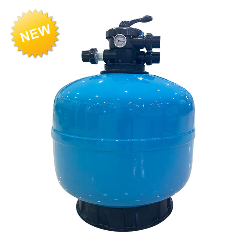
4 Ways Top Mount Configurations Simplify External Filter Piping
Solution Categories & Approaches
Top-mount designs offer specific plumbing advantages that tackle spatial, hydraulic, and mechanical challenges directly on the job site. When laying out a new equipment pad, builders look for ways to minimize pipe usage and reduce the number of fittings. We break down these four specific benefits below to show how they improve system longevity and make the installer's job easier.
1. Elimination of Complex PVC Manifolds
The integrated valve removes custom-built external pipe webs entirely. You do not need multi-directional manifolds to route water into the top of the tank and out of the bottom. The valve handles all flow direction internally through its rotor and spider gasket assembly. This simplifies the visual layout immediately, making troubleshooting much easier for service technicians. Operators can trace lines without confusion because the plumbing paths are linear. Side-mount systems often look like a maze of pipes, especially when bypass loops for heaters and UV systems are added. Top-mount systems offer a clean, straightforward look. You connect the pump discharge directly to the intake port. You connect the return port directly to the downstream equipment. You connect the waste port to the designated drain line or backwash pit. The simplicity reduces installation errors and saves hours of labor during the initial build.
2. Shorter Pipe Runs and Reduced Friction Loss
Direct pump-to-valve routing improves hydraulic performance by shortening the overall distance water must travel. Water encounters fewer directional changes, which is critical for maintaining flow velocity. Every 90-degree elbow adds resistance, increasing the dynamic head pressure on the system. Lower friction loss means the pump works less to move the same volume of water. This saves energy over time, especially when paired with a variable speed pump running at lower RPMs. Operating at lower pressures extends the life of the pump motor and the internal seals. Shorter pipe runs also cost less in materials. You buy less Schedule 40 PVC pipe and fewer slip fittings. The entire hydraulic loop becomes more efficient, allowing you to achieve the required turnover rate without upsizing the pump unnecessarily.
3. Centralized Intake and Output Positioning
Centralized ports simplify pipe measuring and cutting. The pump intake, pool return, and waste line sit together at a single elevation point on top of the tank. This makes alignment straightforward and prevents the awkward staggered pipe runs common with side-mount setups.
Measure the vertical rise from the pump discharge to the valve intake accurately using a laser level or plumb bob.
Align the valve ports toward their respective destinations before applying any PVC primer or cement.
Install half-union fittings directly into the valve ports to allow for easy removal and future servicing.
Keep the waste line path clear of foot traffic to prevent tripping hazards on the equipment pad.
Leave at least six inches of straight pipe before the intake port to reduce turbulence entering the valve.
Support long horizontal pipe runs with adjustable stands to prevent sagging and stress on the valve neck.
These practices optimize the equipment pad layout and minimize the need for offset fittings. Centralized positioning speeds up the installation process and results in a professional, symmetrical appearance.
4. Minimizing Potential Leak Points
Bypassing side-mount external plumbing reduces glued joints and threaded fittings significantly. Every elbow, tee, or union represents a potential leak point that can fail due to ground shifting, vibration, or poor gluing technique. A top-mount design can eliminate dozens of these connections from the filtration loop. Fewer joints mean a drier equipment pad and reduced long-term maintenance tasks. PVC cement degrades over time, and threaded connections can vibrate loose from the constant hum of the pump motor. By reducing the total number of connections, you reduce the overall risk of system failure. The setup becomes inherently more reliable. Facility managers spend less time chasing small drips and puddles, allowing them to focus on water chemistry and patron safety.
Evaluation Dimensions: Scalability, Footprint, and Performance
Features-to-Outcomes
Top-mount features map directly to operational benefits on the ground. Vertical integration solves horizontal space issues, while internal routing solves hydraulic friction problems. We must evaluate these features against actual performance needs to ensure the selected equipment matches the facility's demands.
Compact Design for Tight Equipment Pads
Constrained mechanical rooms benefit immensely from vertical designs. Consolidating the valve saves critical horizontal space, making retrofits much easier in tight enclosures. You can fit larger diameter tanks into smaller footprints, which helps when upgrading older, undersized equipment to meet modern turnover codes. Many older pools have tiny equipment sheds built decades ago. A bulky side-mount filter simply will not fit through the door or sit on the existing concrete pad. The top-mount design utilizes dead vertical space, leaving room for modern additions like heat pumps, salt chlorine generators, and automated chemistry controllers. It provides better physical access for technicians performing routine maintenance tasks, reducing the likelihood of accidental damage to surrounding equipment.
Hydraulic Limits and Flow Rates
Top-mount valves have realistic flow rate limitations that builders must respect. Large-bore side-mount configurations handle massive water volumes better because they can accommodate 3-inch or 4-inch plumbing. Top-mount valves typically max out around 2 to 2.5 inches in port size. This port size restricts maximum turnover rates and dictates the maximum gallons per minute the system can handle. You must match the valve capacity to your pump output. Exceeding this limit causes excessive backpressure, which damages the pump impeller and forces dirt straight through the media bed. You must calculate your required flow rate based on the pool volume and desired turnover time. Ensure the top-mount valve and the internal laterals can handle that specific flow without exceeding the manufacturer's maximum pressure rating, usually around 50 PSI.
When to Specify a Commercial Pool Sand Filter
Facilities eventually outgrow standard residential units as bather loads increase. High turnover rates require larger equipment to maintain water clarity and sanitation. Heavy bather loads demand robust filtration that can handle constant debris introduction. A commercial pool sand filter handles these demands through thicker tank walls, reinforced laterals, and higher pressure ratings. You must evaluate valve port sizing carefully when making this transition. Commercial units often use side-mount valves for higher flow, but some manufacturers offer high-capacity top-mount options for medium-sized commercial applications. You must verify bather load compliance and local health department codes before specifying the unit. Commercial health codes dictate strict turnover times, often requiring a full turnover every 4 to 6 hours. If a top-mount valve cannot meet the flow requirement without excessive velocity, switch to a side-mount manifold. Do not compromise flow dynamics for spatial convenience.
Operational Advantages: Multiport Valve Settings Demystified
Overall Value Influencing Factors
Simplified piping translates directly to easier daily operations. Maintenance routines take less time, and operators face fewer confusing valve sequences. The integrated design makes training new staff simpler, as all functions are controlled from a single, clearly labeled handle.
Streamlined Backwashing and Rinsing
The top-mount MPV executes functions seamlessly without requiring operators to manipulate multiple external ball valves or butterfly valves. You simply turn off the pump, press the handle down to compress the heavy-duty spring, and rotate it to the backwash position. You turn the pump back on, and the internal mechanics reverse the water flow. Water travels down the standpipe, out the laterals, and pushes up through the media bed. This lifts the sand and flushes trapped debris out the waste port. The sight glass on the side of the valve shows when the water runs clear. You turn off the pump again and switch to the rinse setting. The rinse function sends water down through the top of the bed and out the waste line. This settles the sand back into place and flushes any remaining dirty water out of the valve body. It prevents a cloud of dirt from entering the pool when you switch back to the filter setting.
Leveraging Piping for Easy Water Changes
The waste setting simplifies pool draining and water level management. It utilizes the existing plumbing architecture to bypass the filter media entirely. Water pumps directly from the pool out the waste line to the sewer or drainage ditch. This eliminates the need for temporary hoses draped across the deck. You do not need separate submersible pumps to lower the water level after a heavy rainstorm. Routine water changes become a simple lever adjustment. Heavy rain often overfills the pool, throwing off the skimmer function and diluting chemicals. The waste setting drops the water level quickly and efficiently. Vacuuming heavy debris, like spring leaves or severe algae, directly to waste is also easy. It prevents the sand bed from clogging prematurely and saves you from having to backwash multiple times during a single vacuuming session.
Recirculate and Closed Functions
The recirculate setting bypasses the media bed completely. It routes water from the pump directly back to the pool return lines. This helps distribute chemicals quickly without trapping them in the sand. It is highly useful when treating severe algae blooms with flocculants or heavy shock treatments. You do not want dead algae or coagulated debris clogging the sand and creating channeling issues. The closed function stops all water flow through the valve. It allows for pump basket cleaning and prevents water from draining out of the filter or flowing backward from the pool if the equipment is located below water level. The internal standpipe design facilitates these settings seamlessly. You need no additional external bypass piping or check valves to achieve these functions. The valve rotor handles all routing internally based on the handle position.
Implementation Risks and Mitigation Strategies
Experience & Trustworthiness
Top-mount systems have realistic downsides and structural limitations that builders must acknowledge. We must address these to ensure proper installation and long-term reliability. Ignoring these risks leads to equipment failure, cracked tanks, and flooded mechanical rooms.
Overhead Clearance Requirements
Vertical space is absolutely necessary for this configuration. You must remove the MPV for lateral repairs, standpipe replacement, or deep cleaning. Media replacement requires unobstructed access to the tank opening. Measure the ceiling height or truss clearance before installation. Ensure you have enough room to lift the valve and the attached standpipe straight up. The internal standpipe is long, often reaching the very bottom of the tank. You must pull it straight up to clear the media. If the ceiling is too low, you cannot remove it without cutting pipes. You would have to disconnect all plumbing, drain the tank, and physically tip the heavy vessel to get the valve out. This defeats the purpose of a simplified setup and turns a one-hour media change into a full-day ordeal. Always verify vertical clearance with a tape measure before committing to a top-mount design.
Alignment and Gluing Precautions
Locking in a poor alignment is a major risk during installation. You must dry-fit all connections before opening the primer. Orient the MPV correctly toward the pump and return lines before applying PVC cement. Once glued, you cannot rotate the valve without cutting the pipe and using couplings.
Top Mount Valve Alignment Checklist
| Step | Action | Purpose |
| 1 | Position Tank | Establish the final resting place on the concrete pad. |
| 2 | Dry-Fit MPV | Check port orientation toward pump and return lines. |
| 3 | Measure Pipes | Ensure straight runs without tension or bending. |
| 4 | Mark Alignment | Draw reference lines across fittings with a permanent marker. |
| 5 | Glue and Hold | Apply cement and hold for 30 seconds to prevent joint push-out. |
Take your time during the dry-fit phase. Rushing the gluing process leads to crooked pipes that do not seat fully into the fittings. Crooked pipes put constant mechanical stress on the valve body, which will eventually cause the plastic to crack under pressure.
Weight and Stress on the Tank Neck
Heavy, water-filled PVC pipes place immense mechanical stress on the filter neck. This can cause hairline fractures over time, leading to catastrophic leaks. Proper pipe support is critical for any top-mount installation. Use adjustable pipe hangers, unistrut, or floor supports for long horizontal pipe runs. Do not let the tank neck bear the dead weight of the plumbing. The clamp ring secures the valve to the tank flange; it is not designed to hold up heavy pipes. Vibration from the pump exacerbates this stress, acting like a hammer on the plastic flange. Install adjustable pipe supports directly under the horizontal runs to transfer the weight to the concrete pad. Winterization presents another challenge. You must drain the tank completely before freezing temperatures arrive. Top-mount tanks feature a bottom drain plug for this purpose. However, the multiport valve also holds water in its internal chambers. You must blow out the lines with an air compressor and rotate the valve handle to the winterize position. This lifts the internal diverter seal, preventing trapped ice from expanding and cracking the valve body.
Evaluating a Sand Filter Manufacturer
Select vendors based on structural integrity and material quality. Look for flange durability and a robust clamp ring design. A reliable sand filter manufacturer provides strong warranty terms and uses high-grade thermoplastics or fiberglass winding. Check their policy regarding neck stress fractures, as this is the most common failure point. High-quality materials prevent catastrophic failures at the connection point. Cheap plastics become brittle in the sun and crack under normal operating pressures. Look for UV-resistant tank materials if the equipment will be installed outdoors. Ensure the internal standpipe is thick-walled Schedule 40 PVC or better. The laterals should fold up easily for maintenance and feature reinforced hinges. Read reviews from other pool professionals to gauge long-term reliability in the field.
Conclusion
Top-mount configurations drastically reduce external plumbing complexity by internalizing water routing. They eliminate messy manifolds, reduce hydraulic friction loss, and save valuable horizontal space on the equipment pad. However, they require greater vertical clearance for maintenance and have strict flow rate limitations based on port size. Choose a top-mount design for constrained horizontal pads and standard flow rates. Choose a side-mount design for high-flow applications requiring frequent media changes or massive turnover volumes.
Measure your equipment pad's vertical clearance to ensure at least 24 inches of overhead space above the tank apex.
Calculate your required system flow rate based on total pool volume to ensure it does not exceed the valve's maximum capacity rating.
Consult with a certified supplier to match valve port sizing to your existing underground plumbing lines.
Inspect your current setup for unnecessary elbows and potential leak points that can be eliminated during the retrofit.
Install adjustable pipe supports under heavy PVC runs to protect the tank neck from mechanical stress.
FAQ
Q: What is the primary difference in plumbing a top mount vs. side mount sand filter?
A: A top mount filter integrates the multiport valve directly on the tank apex, eliminating external lateral piping and bulkheads. Side mount filters require external PVC manifolds to connect the valve to the side of the tank, which takes up significantly more horizontal space on the equipment pad.
Q: Does a top mount multiport valve restrict water flow in a swimming pool filtration system?
A: It can restrict flow in very high-volume setups. Top mount valves typically max out at 2 to 2.5-inch port sizes. While efficient for standard residential use, massive pools may require side mount configurations with larger bore piping to prevent backpressure and pump damage.
Q: How much overhead clearance is required to maintain a top mount sand filter?
A: You generally need at least 18 to 24 inches of clearance above the valve. This vertical space is necessary to lift the multiport valve and the attached internal standpipe straight out of the tank for sand replacement or internal lateral repairs.
Q: Can I use the waste setting on my top mount valve for routine pool water changes?
A: Yes. The waste setting directs water from the pump straight out the waste line, bypassing the sand bed entirely. This utilizes your existing plumbing architecture to drain the pool quickly without needing temporary hoses or separate submersible pumps.
Q: Can I retrofit my existing side-mount plumbing to accommodate a top-mount valve?
A: Yes, but it requires repiping the equipment pad. You must route the pump discharge up to the new valve height and adjust the return line accordingly. Ensure your mechanical room has the necessary vertical clearance before attempting this retrofit.
Q: What causes leaks at the neck of a top mount filter, and how can they be prevented?
A: Leaks often occur due to mechanical stress. Heavy, unsupported, water-filled PVC pipes pull on the valve and crack the tank flange. Prevent this by installing proper pipe hangers or floor supports so the tank neck does not bear the plumbing weight.
Q: Are top mount configurations available for a commercial pool sand filter?
A: Yes, some manufacturers produce high-capacity top mount filters for commercial use. However, you must carefully match the valve port sizing to your required turnover rates to ensure bather load compliance. Side mounts remain more common for extreme flow requirements.


